
HOW IT WORKS
BASIC PROPELLER FUNCTIONS
The controllable pitch propeller is designed to maintain constant engine speed by adjusting propeller blade angle to vary the load on the engine in response to the changing conditions of flight.In the most common type of hydraulic propeller, a piston and cylinder are linked to the propeller blades so that when oil under pressure is pumped to this cylinder, the piston and the blades are forced to move. Movement of the propeller piston rotates the propeller blades of an uncounterweighted propeller in the increase pitch direction and the blades of a counterweighted propeller in the decrease pitch direction. The single acting propeller thus uses oil pressure to change pitch in one direction and the centrifugal force of propeller counterweights, air charge or the natural twisting movement of the blades to change the pitch in the other direction.
At the feathering type propellers, a spring load is composed to complete the feathering cycle as rotation speed and counterweight force diminishes.
METHODS OF SPEED CONTROL
On most governed engines, the governor maintains constant engine rpm by moving the throttle to control fuel supply to the engine and match power output to the load. In the case of the aircraft engine, the propeller is the load and power developed is determined by the pilot. The function of the propeller governor is to adjust the propeller blade angle so the load on the engine will maintain the desired engine rpm at the horsepower setting selected.For example, the propeller will absorb full take-off power and give maximum thrust during the take-off run and will not Overspeed as the airspeed increases because of increased blade angle. The advantages in performance, safety and convenience are obvious. The increase in aircraft horsepower and speed has made a constant speed control necessary in order to derive full advantage from improved engine and aircraft performance over a wide range of operating conditions. The propeller control lever determines the governor speed setting. The propeller pitch is controlled by the governor. Thus if the governor speed setting is increased, the governor decreases the propeller pitch until the engine speed increases to the new rpm setting. The actual blade angle required for given rpm depends on the horsepower being developed and the airspeed of the aircraft. However, the governor senses only RPM.
LIMITS OF GOVERNOR CONTROL
Given rpm can be maintained by the governor providing there is power enough to turn the engine at the governor speed setting. Whether this engine power or propeller power matters not to the governor, whether the engine drives the propeller or the propeller drives the engine – the governor operation is the same.With the governor set for 2300rpm, propeller pitch is adjusted by the governor to maintain this speed, regardless of throttle position or airspeed, within the pitch range of the propeller.
Near cruising airspeed, the propeller on most constant speed installations can develop sufficient torque to drive the engine at cruise rpm even if the engine is completely inoperative. This of course is the reason it is necessary to feather the propeller of inoperative engine on multi-engine aircraft because of the high drag of a windmilling propeller turning an inoperative engine.
As the throttle is slowly closed in flight, the propeller pitch will decrease and 2300 rpm will be maintained until the propeller blades reach their low pitch position. Any further reduction in power or airspeed will cause a decrease in engine rpm.
Whenever the actual engine rpm drops below the governor speed setting, the propeller is in the low pitch position and the rpm can be controlled with the throttle.
During an approach, as the airspeed is decreased at low power setting, the propeller will be in it´s extreme low pitch position and rpm can be controlled with the throttle. Under this condition, rapid throttle burst will cause a momentary Overspeed above the governor speed setting. The amount of Overspeed in any installation depends upon the rate of throttle movement, and the increase in propeller pitch necessary must be increased to maintain the desired rpm. The more rapid the throttle movement, the higher the speed and the lower the governor setting, the larger the overspeed will be.
The amount of Overspeed is determined by the governor flow rate, i.e., the volume of oil the governor with port for a given Overspeed, and the force available from the propeller counterweights, to increase the propeller pitch.
Rapid rate of pitch change is especially noticeable if the throttle is closed at high airspeed as there will be very little engine speed change.
GOVERNOR operation
The sensing element of the governor is a set of pivoted flyweights mounted on a rotating flyweight head and linked mechanically to the engine gears, through a hollow drive gear shaft.
The flyweights, actuated by the centrifugal force developed by the speed of the rotation, position a pilot valve so as to cover or uncover ports in the drive gear shaft and regulate the flow of oil to and from the pitch changing mechanism of the propeller. The centrifugal force exerted by the flyweights is opposed by the force of an adjustable speeder spring. The load exerted by the speeder spring determines the engine RPM required to develop sufficient centrifugal force in the flyweights to center the pilot valve. Oil to operate the propeller’s pitch changing mechanism is supplied by a gear-type oil pump at a pressure value limited by a relief valve.
The schematic governor arrangement is at Fig. 1
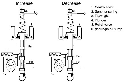
Fig.1.
Governor operation represents basically three conditions – on speed, overspeed and underspeed.
ON SPEED
In this condition the forces action on the engine-governor-propeller combination are in a state of balance. The speed adjusting control lever has been set by the pilot to obtain the desired engine RPM.The propeller blades are at the correct pitch to absorb the power developed by the engine. The centrifugal force of the rotating flyweights exactly balances the force of the speeder spring with the flyweights in the vertical position. The pilot valve is positioned in the drive gear shaft, so that the control ports between the oil pump and the propeller pitch changing servo are covered. Pressure oil from the gear pump is circulated through open governor relief valve back to the inlet channel of the pump.
OVERSPEED
This condition occurs when airspeed or horsepower is increased and engine RPM increases above the rate called for by the setting of the speed adjusting control lever. The rotating flyweights pivot outward as their increased centrifugal force overcomes force exerted by the speeder spring.Counterweighted Propeller using Pressure to Decrease Pitch (see Fig. 2)
The flyweight toes raise the pilot valve plunger, uncovering ports in the driver gear shaft that permit pressure oil to flow from the propeller pitch changing mechanism. This allows propeller counterweights to take the propeller blades towards a higher pitch. The load on the engine is increased and engine speed is reduced.
Uncounterweighted Propeller using Pressure to Increase Pitch (see Fig. 3)
The flyweight toes raise the pilot valve plunger, uncovering ports in the driver gear shaft that permit pressure oil to flow to the propeller pitch changing mechanism. This moves the propeller blades to a higher pitch and load on the engine is increase and engine speed is reduced.
This, in turn, lessens centrifugal force exerted by the flyweights in opposition to the force of the speeder spring. The flyweights return to a vertical position and the pilot valve plunger once more covers ports in the drive gear shaft, blocking flow of pressure oil to or from the pitch changing mechanism of the propeller.
UNDERSPEED
An underspeed condition occur when the airspeed or horsepower is decreased and engine RPM falls below the rate established by the setting of the speed adjusting control lever. The decrease in the centrifugal force of the rotating flyweights causes them to pivot inward under the force exerted by the speeder spring.
Counterweighted Propeller using Pressure to Decrease Pitch (see Fig. 2)
The pilot valve plunger is forced down uncovering the ports in the drive gear shaft that allow pressure oil to flow to the pitch changing mechanism of the propeller. This overcomes the force of the propeller counterweights and decreases the pitch of the propeller blade.
Uncounterweighted Propeller using Pressure to Increase Pitch (see Fig. 3)
The pilot valve plunger is forced downward, uncovering the ports in the driver gear shaft, thus allowing oil to flow from the pitch changing mechanism of the propeller to sump. This permits the centrifugal twisting moment of the blades to decrease propeller pitch.
This reduce the load on the engine, thereby increasing engine speed and the centrifugal force developed by the rotating flyweights. The flyweight toes lift the pilot valve plunger to cover the control ports. At this point the forces acting on the engine-governor-propeller combination are again balanced an the engine is back to the speed called for by the governor setting.
Pressure to decrease pitch Type Pilot Valve
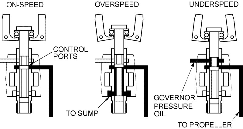
Fig. 2
Pressure to increase pitch Type Pilot Valve
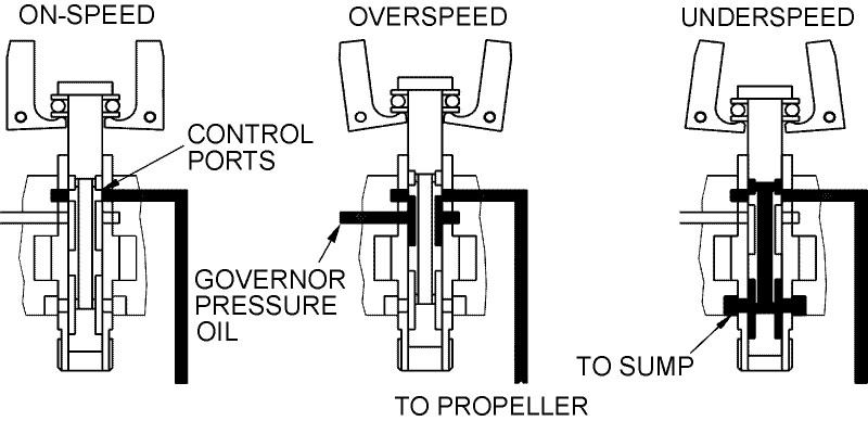
Fig.3
CLICK TO ENLARGE Description of origin and distribution of JIHOSTROJ designed propeller governors.
